Hannibal
Well-known member
In replacing the top portion of my helm - I had to remove the guages and remove the wiring. I took plenty of pictures and even drew a diagram showing the wiring colors/paths. However, as it always the case, you don't know what details are truley most important until you realize you didn't include them in your notes. As such, I've discovered that my pics and sketch don't answer all my questions in getting the gauges back up and running.
I've googled and done some reading but everything seems much simpler than what I am dealing with.
For example:
While I have a pic of the particular gauge - it doesn't show me where each wire goes to/originates from. After tinkering with it a while, I understand that all the gauges are connected in line but it still doesn't work.
Couple of things I could use some better understanding of:
1) Where does the main power come from? I don't recall a main possitive line being connected to the gauges anywhere. And would I even want a full time power source to them? Shouldn't they be pulling power from the ignition source so that they are only on when the boat is on?
2) Where would the ignition source/hot be located? I have SOOOO many wires dead-ended behind the helm (likely from the previous owner's repower) that I am not sure what is what honestly. I have a cable cluster (following the main cable bundle) that is wrapped that includes a black/purple/white wire. Could this be it? Under a previous attempt, I had the purple wire feeding a + on the gauges with the black serving as ground. But I had no home for the white (and nothing on a pic or sketch showing it's connection point).
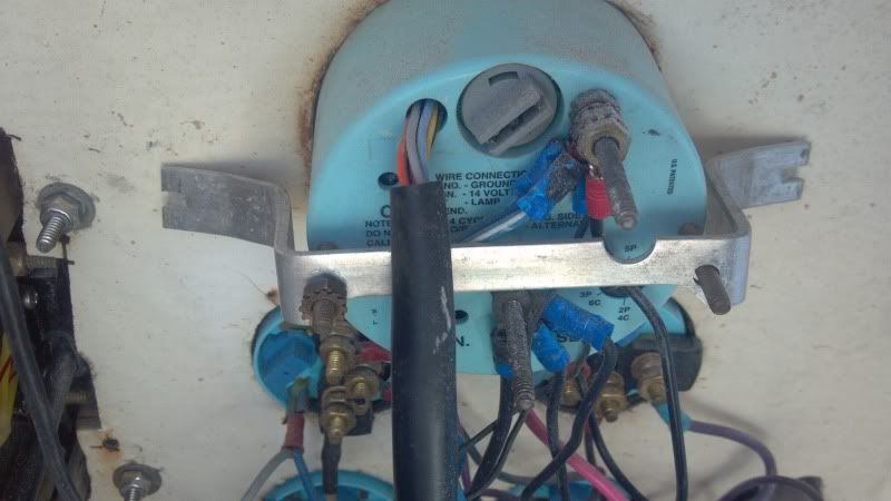
3) Off the main tachometer/all-in-one system check gauage, there are two posts and one harness. The harness is a no brainer. The lower post clearly says ground, however, the top post says nothing. And on the pics and the sketch - it had black wires running from it. But this either means someone got lazy with their colors or there is some other ground (and it's pulling power from the harness). When I turn the boat on - they system check lights up and beeps like it normally does. However, the tach doesn't work. Does it gets its information from the harness or am I missing a sending wire? Again, there are two posts - one I would assume as possitive/ignition, the other as ground. There is no "source/sending" post and I would assume it's getting it's power from the harness.
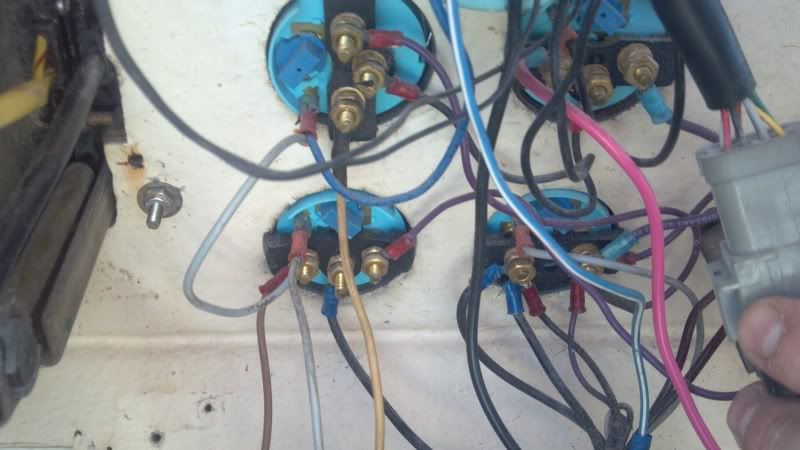
4) Off the main ground on the tach/all-in-one - there is a black/ground wire running to all the other (4) gauges. This to me serves as their ground contact. However, they are then looped/connected in series between them (a ground wire goes from gauge to gauge completing a loop). Is this normal or would it possibly create some kind of block? In other words, it's being grounded from two sources/wires. Sounds odd to me but I am no expert with electricity and it isn't working.
Now, in reading, I understand the basic theory of it all. Each gauge should have a power contact, a ground contact and a sending/info. contact. With my battery/volt gauge - there are only two. I am assuming this is because the possitive/power feed provides the gauge with the information it needs. However, even in simply hooking up the possitive/ground - it still doesn't move. And I have power to the main line and a ground bar right there. Then again, I didn't direct wire them to the gauge so maybe I need to .............
Maybe this is better solution ................
1) Where can I pick up the ignition/power source? What color is the wire?
2) Is the exposed black wire coming from the smaller wire cluster (with the purple, white wires) a ground? I would assume. Or should I directly run to the ground bar I mounted?
3) For my motor (if not standard) - Evinrude ....... what color are the sending wires for:
a. Temp.
b. RPM (if not done through the wire harness).
c. Voltage (if not done directly off the possitive feed).
d. Trim (never preiously connected).
e. Fuel level.
Any help would be appreciated. I am trying to finish up this project and avoid having to hit the marine mechanic.
I've googled and done some reading but everything seems much simpler than what I am dealing with.
For example:
While I have a pic of the particular gauge - it doesn't show me where each wire goes to/originates from. After tinkering with it a while, I understand that all the gauges are connected in line but it still doesn't work.
Couple of things I could use some better understanding of:
1) Where does the main power come from? I don't recall a main possitive line being connected to the gauges anywhere. And would I even want a full time power source to them? Shouldn't they be pulling power from the ignition source so that they are only on when the boat is on?
2) Where would the ignition source/hot be located? I have SOOOO many wires dead-ended behind the helm (likely from the previous owner's repower) that I am not sure what is what honestly. I have a cable cluster (following the main cable bundle) that is wrapped that includes a black/purple/white wire. Could this be it? Under a previous attempt, I had the purple wire feeding a + on the gauges with the black serving as ground. But I had no home for the white (and nothing on a pic or sketch showing it's connection point).
3) Off the main tachometer/all-in-one system check gauage, there are two posts and one harness. The harness is a no brainer. The lower post clearly says ground, however, the top post says nothing. And on the pics and the sketch - it had black wires running from it. But this either means someone got lazy with their colors or there is some other ground (and it's pulling power from the harness). When I turn the boat on - they system check lights up and beeps like it normally does. However, the tach doesn't work. Does it gets its information from the harness or am I missing a sending wire? Again, there are two posts - one I would assume as possitive/ignition, the other as ground. There is no "source/sending" post and I would assume it's getting it's power from the harness.
4) Off the main ground on the tach/all-in-one - there is a black/ground wire running to all the other (4) gauges. This to me serves as their ground contact. However, they are then looped/connected in series between them (a ground wire goes from gauge to gauge completing a loop). Is this normal or would it possibly create some kind of block? In other words, it's being grounded from two sources/wires. Sounds odd to me but I am no expert with electricity and it isn't working.
Now, in reading, I understand the basic theory of it all. Each gauge should have a power contact, a ground contact and a sending/info. contact. With my battery/volt gauge - there are only two. I am assuming this is because the possitive/power feed provides the gauge with the information it needs. However, even in simply hooking up the possitive/ground - it still doesn't move. And I have power to the main line and a ground bar right there. Then again, I didn't direct wire them to the gauge so maybe I need to .............
Maybe this is better solution ................
1) Where can I pick up the ignition/power source? What color is the wire?
2) Is the exposed black wire coming from the smaller wire cluster (with the purple, white wires) a ground? I would assume. Or should I directly run to the ground bar I mounted?
3) For my motor (if not standard) - Evinrude ....... what color are the sending wires for:
a. Temp.
b. RPM (if not done through the wire harness).
c. Voltage (if not done directly off the possitive feed).
d. Trim (never preiously connected).
e. Fuel level.
Any help would be appreciated. I am trying to finish up this project and avoid having to hit the marine mechanic.