Nav & Anchor light wiring

Classic Parker Boat Forum

Help Support Classic Parker Boat Forum:

This site may earn a commission from merchant affiliate links, including eBay, Amazon, and others.

SBH2OMan

Well-known member
Joined
Oct 23, 2010
Messages
552
Reaction score
10
Location
Santa Barbara, CA
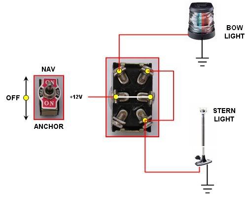
OK, in my stem-to-stern rewire project this past winter I just discovered something I messed up. (amazingly, its the only thing that doesn't work after I finished!)

I thought I was very clever and moved the stacked spade connectors on the back of the Nav/Anchor light switch to a separate "lighting bus" that is basically energized when I flip the switch to the "Nav" position. Unfortunately, because I left the only connector for the anchor light attached to the "Anchor" position of the switch, when I flip on the Nav lights, everything works except for the all-around light. It does work when I flip it to the Anchor position.

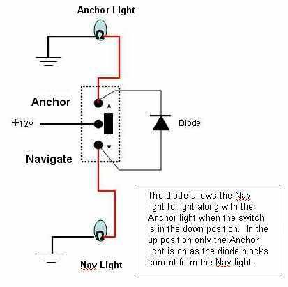
Now, I have to assume that originally there was a "bridge" of some sort between the anchor and nag positions on the switch, but a simple jumper wire would "back-flow" electricity to the Nav circuit when the anchor light was turned on, unless there was some sort of diode preventing this.

I certainly would have noticed a diode when I pulled everything out, which I did not, so I'm a bit stumped.

Any suggestions on how to activate just the anchor light without turning on all the nav lights when the switch is in the Anchor position, but still have the anchor light come on WITH the nav lights?

By the way, the "lighting bus" sends power to the interior dash lights, the small cockpit step lights, and the side lights when the switch is in the Nav position.
 
You mean there's nothing connected to the NAV pole on the Nav/Anchor Light switch? If so, add a run from your lighting buss to that pole.

Or, it sounds like your Nav switch is supplying power to the buss but not to the light terminal ...
 
DaleH":f8kpl5rq said:
You mean there's nothing connected to the NAV pole on the Nav/Anchor Light switch? If so, add a run from your lighting buss to that pole.

Or, it sounds like your Nav switch is supplying power to the buss but not to the light terminal ...


I guess I'm not doing a good job describing the situation. Let me try again:

There is a single wire in the harness for "Anchor" and a single wire for "Navigation" which each run out to their respective lamps on the boat. Originally there were a stack of "piggyback" connectors on the "Navigation" pole of the switch, to which were added the compass light, the dash lights, and a few other things in addition to the "Navigation" wire. I just moved all of those to a bus bar and then ran a single wire from the "Nav" pole of the switch to the bus bar. When the switch is flipped to the Nav position, it powers the bus to which all the navigation lighting is attached, but not the all-around light on top (which is required). My concern is that if I make a jumper wire from the bus to the anchor light wire (which is attached to the "Anchor" pole of the switch) in an attempt to light the all-around light with the nav lights, power will "back flow" from the anchor pole of the switch and light up all the nav lights when all I want is the mast head/all-around (anchor) light. In other words, when flipped to "Nav" all lights will light, but when flipped to "Anchor" all lights will also light because of the jumper wire... Typically the way to prevent this is with a diode, but I didn't see anything soldered to the back of the switch or in series with the wires I replaced... (I would have noticed something like that!)

Does that make more sense?
 
I just happen to have the wiring diagram to my 1997, 2320 and it does show a diode, although I have never noticed it.
 
Scalawag 2320":txkk5lgo said:
I just happen to have the wiring diagram to my 1997, 2320 and it does show a diode, although I have never noticed it.

Aha! The smoking gun... now the question is where it is physically located...
 
I'll try one more time.
If it does not work Robin Parker will send it to you if you ask her nicely.
OK she is nice you can just ask.
The diode maybe internal of the switch
 

Attachments

  • parker wire doc compressed.jpg
    parker wire doc compressed.jpg
    148.8 KB · Views: 174
Hmmmmmmmm! I've never seen a diode in a lighting switch.

It calls for a DPDT switch.
Circuit6.jpg


It's a little long but it gets the point across.

http://www.youtube.com/watch?v=8huxz1mmAtA
 
That video almost perfectly illustrates my question. I see now that if it is a DPDT switch (which I assumed mine was not) then the anchor and nav circuits are separated. I'm still wondering about back-flow across the completed circuit however.

Its kinda hard to tell from the angle of this shot, but here is what my panel looked like before the re-wire. You can see how on the left everything is just stacked up on those brass "piggy-back" connectors (argh!).

Circuit_Panel_Snip.jpeg


I obtained a schematic for my particular HIN, and here is the part in question:
Schematic_Snip.jpg


Clearly, there is a diode indicated in the schematic, which I have to assume is a "blocking" diode intended to prevent the back-flow of voltage across the switch.

I'm 300 miles away from the boat, but it looks like I have enough info to know what I'm looking at when I return on Friday. Either way it appears to be a relatively easy fix.
 
Look at the terminals on that schematic. It's not a DPDT switch. The DPDT has 6 terminals [+ 1 if it is a lighted switch]

The one in the schematic appears to be a SPDT and the reason there is a diode in there. I've never seen that before.

The standard is DPDT switch.
 
Just to settle this topic for the benefit of others in the future, there is apparently two common ways of doing this around the world. One is with a DPDT switch, and the other is with a SPDT switch and diode. Apparently my Parker originally came with a SPDT switch and diode, but I mistakenly replaced the switch with a regular SPDT switch (lacking the diode). I will now replace with a DPDT switch, since I can't find one with an integrated diode and I don't want to deal with soldering a diode onto the switch.

If using a 6 terminal (DPDT) switch, wiring looks like this:
NavSwitchWiring.jpg


If using a SPDT switch, wiring looks like this:
Nav-AnchorSwitch.jpg


Credit for the illustrations goes to "silvertip" on the iBoats forums.

Note, that this applies only to boats that don't have a "combo" lighting unit (where the port/starboard side lights and all-around light are in a cluster and wired together)

Another good article can be found here (but I think the diagrams are more confusing)
http://www.bluesea.com/articles/104
 
I just went through this on my boat, there is a diode on mine. Long story short I burned it out relocating my anchor light and found a replacement at radio shack for 1.99.

You can see it in the pics.

Second pic was me testing the new diode to see if that was the problem, it was.

Don't waste your money on a new switch, diode way cheaper and easier. Wish I would have seen this post sooner.
 

Attachments

  • IMG_2181.JPG
    IMG_2181.JPG
    269.8 KB · Views: 111
  • IMG_2185.JPG
    IMG_2185.JPG
    265 KB · Views: 111
A new DPDT switch is only about $7 ($9 with shipping) and considering the time to go to the store and rigging the double spade terminals and whatnot, its probably cheaper for me to just go with the replacement switch. :)
 
Back
Top