Bilge wiring Rule 1500

Classic Parker Boat Forum

Help Support Classic Parker Boat Forum:

This site may earn a commission from merchant affiliate links, including eBay, Amazon, and others.

JET O_Wey

Well-known member
Joined
Jun 21, 2009
Messages
50
Reaction score
1
If someone could be so kind as to sketch the proper wiring for my primary bilge it would be greatly appreciated. Wiring is not my specialty so want to make sure I get this correct. Bilge is Rule 1500. Not pictured in-line fuse.


JET

(need to move post to electrical)
 

Attachments

  • float wires.JPG.png
    float wires.JPG.png
    161.9 KB · Views: 427
  • float.png
    float.png
    162 KB · Views: 427
  • Pump specs.png
    Pump specs.png
    93.8 KB · Views: 427
  • Pump wire colors.png
    Pump wire colors.png
    114.4 KB · Views: 427
  • Helm switch.png
    Helm switch.png
    127.5 KB · Views: 426
Check that switch 1st on the dash panel. Is that a 2-way or 3-way switch? The 2-way is simple ON or OFF, where the ON side is a momentary switch where if you let it go, it goes back to OFF.

A 3-way swith is OFF in the center position, a click to ON to the automatic side (pump goes ON when the float switch is activated by rain or bilge water) and when click to the ON position the pump runs ON as long as you hold the switch (momentary switch).

2-Way
Bilge pumps are simply wired so they have two power source paths, one via the helm switch to manually turn it on, the other automatically via a float. As you can see, the DC power can get to the bilge pump via the two paths - from battery to helm switch then to pump, or from battery to float to pump. The power for the automatic side of the bilge pump should be either wired directly to the battery, or to a hot bus near the battery and will have a fuse inline.

3-Way
Adds a circuit up the helm to put into auto operation. In the 2-way you can only cycle it ON or OFF.
 

Attachments

  • Basic Bilge Pump Wiring, 2-way.gif
    Basic Bilge Pump Wiring, 2-way.gif
    13.3 KB · Views: 414
  • Rule 3-Way Bilge Pump Wiring.gif
    Rule 3-Way Bilge Pump Wiring.gif
    60.4 KB · Views: 415
I added a wiring sketch - does it look OK?
 

Attachments

  • Sketch wiring bilge.png
    Sketch wiring bilge.png
    62 KB · Views: 393
My top circuit posted shows the wiring for an OFF and ON (momentary) switch. This allows the float switch to cycle the pump or for you to run it OR test it.
 
Your sketch is the Norm.

The ON/OFF switch at the helm gets power when the battery switch is turned ON. I've seen a [Momentary] switch only once there.

The OFF position is actually the AUTO position. This is due to that switch being in the OFF position, but the Float switch still has Power available via a Inline fuse direct from a battery.

Most people will just tie the connections all together with Crimp/Shrink connectors and if your lucky a additional piece of heatshrink w/ glue over that or some Liq elec tape covering the Crimp Shrink.

I don't like doing it that way. It works, but when you have a failure trouble shooting is impossible without cutting it all apart or piercing the insulation with a test light.


So...What to do?

The wiring on all this stuff is usually long enough to get a terminal board high in the bilge.

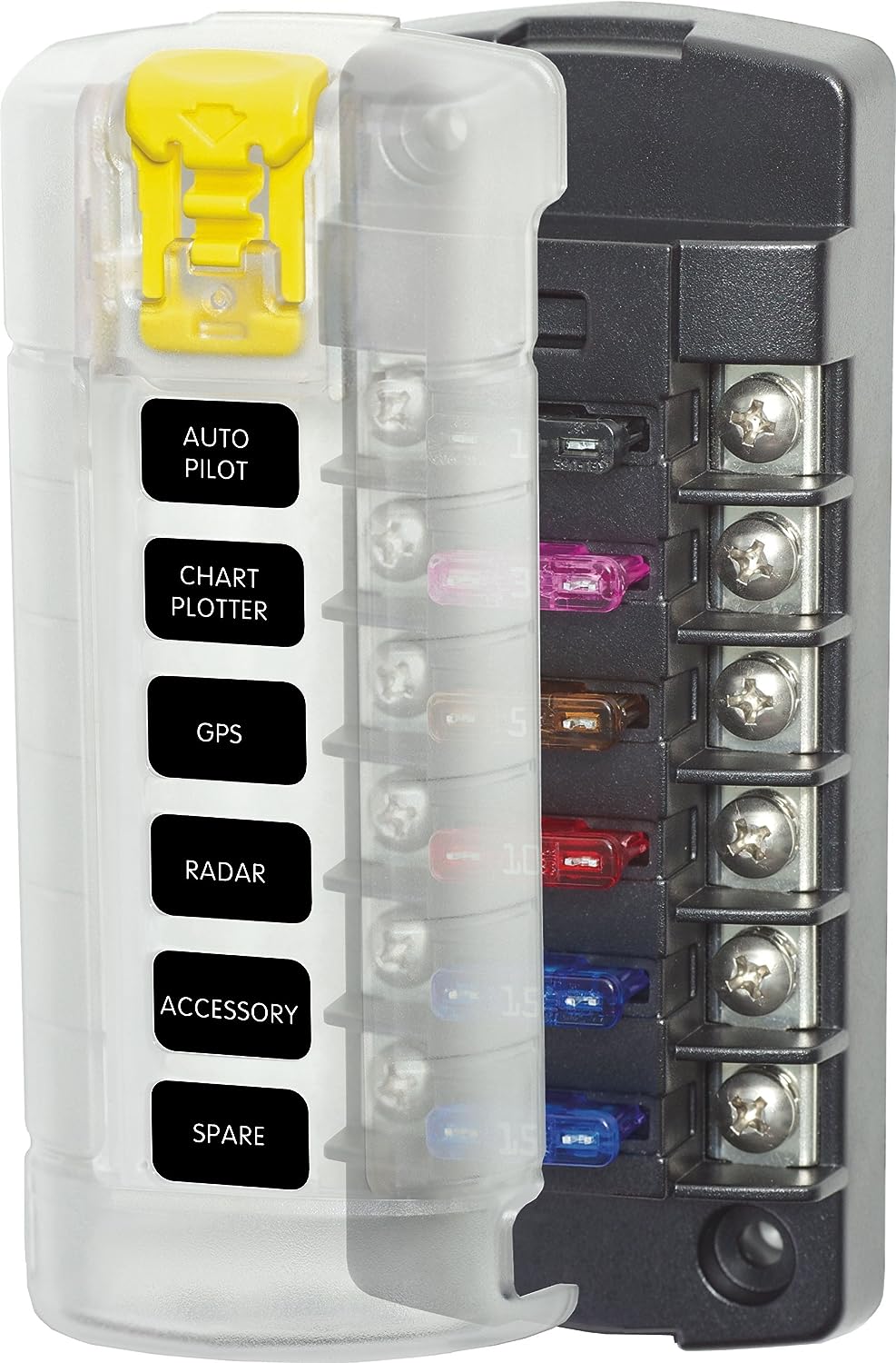
This Blue Seas product is fairly new and I've started using it to power items in the aft area.

http://www.amazon.com/Blue-Sea-Systems- ... e+sea+5035

812YyEbJUJL._SL1500_.jpg


I also use a terminal board.

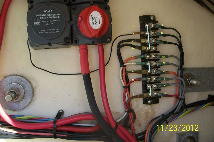
This is one of the things I take the time to add on a wiring job. This is a terminal board that all the connections are made for the pumps. In this case ....The 1500 Bilge pump and the 2000 backup Bilge pump.

bilgewiring.jpg


All the connections are made here. This makes it easy to diagnose a problem in the future and also easier to do a replacement part. With the normal way I see them, there is no way to test a component unless you stab thru the insulation or cut the piece out of the system and check it.


A J
B K -------- All Grounds
C L
D
________
E = Fused Power from Start Batt for 2000GPH pump M= Wire from Float switch
F = Power wire to High Water Alarm [at Helm] N= Wire from float switch
G = Power from Switch panel @ Helm to 2000GPH pump [Manual switch] O=Hot lead to bilge pump2000
H = Fused power from House Batt for 1500GPH pump P= wire from float switch
Q= wire from float switch
I = Power from Switch panel @ Helm to 1500GPH pump [Manual switch] R=Hot lead to bilge pump 1500

The light Blue lines show where jumpers were installed.
 
I see now that u have a lot of time on your hands wart and FYI I powder coated those backing plates for the platform. But great advice. Blue sea products are great. Very easy to use.
 
Looks good! Another tip is to add strips like that in a tupperwear container that is screwed to the transom. Add rubber 'donut' grommets thru the sides and you're protected. Snap off the lid for service and/or checking.

Works SLICK! A poor man's NEMA weatherproof box ;) !
 
Gentlemen-

Key point - electrical is not my specialty, hard to apply concepts to actual. I re-posted my sketch rotated for easier viewing. Would this work?

Respectfully submitted-

JET
 

Attachments

  • Sketch wiring bilge.png
    Sketch wiring bilge.png
    82.9 KB · Views: 335
All good here except for one thing that gets debated all the time on boat forums...
Do I fuse the bilge pump or not?

On my boat, I fuse everything except the bilge pump(s).
In a time of need, I do not want to be dead in the water because a $0.15 part decided to blow.
Fuses are there to protect the wire, not the part.
If I have water coming in, I want the part to work... no matter what.

It's a personal preference decided by the risk involved.
I'm a believer that a fused bilge pump assumes greater risk in an emergency.

As I said... it's a hotly debated topic.
YMMV

Edit: I have no issue with anyone who fuses a bilge pump.
I'm just pointing out that there is risk involved, and my preference is not to assume that risk.
 
Brent":22n3oto9 said:
You could add high water alarm and backup pump

True, and I have both on my boat. High water alarm, and a second 1500 gph backup pump.
I also have bilge pump counters that will count how many time a pump has cycled...

Seemed like a great idea at the time, but I did not realize that the counters 'poll' the pumps constantly, thereby using current all the time.
Not an issue for a boat that is always plugged into shore power, but mine only gets plugged in when the batteries need a top-off.

These days the counters are only active when a nor`easter or a hurricane visits.
During those times, the batteries are plugged in to keep everything topped off and the counters tell me how many times (if at all) the pump(s) activated. :wink:
 

Attachments

  • counters.jpg
    counters.jpg
    1 MB · Views: 266
Back
Top