


seabob4
Active member
Gentlemen,
I've been wiring boats at the OEM level for 16 years, as well as all the rewires, installs, and repairs in my side business. I have found the multimeter to be the tool I use the most, especially when it comes to troubleshooting.
Multimeter Basics
The Multimeter is probably the most important tool in your toolbox when you own an older boat. Over time, so much crap goes wrong electrically with your boat, it is almost impossible to troubleshoot and track down the causes of failures without one.
Now to some who have limited electrical experience, a multimeter may look daunting, when in reality, there are basically 3 functions used on the whole damn dial. DC Voltage, AC Voltage (for those that have shorepower or a generator), and Continuity.
12VDC- Obviously, this setting is used to measure the voltage present in a live circuit, as well as to determine the voltage level of a battery. Very straightforward, simply set the dial to this position...
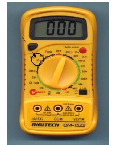
Touch the black probe to a good ground and the red probe to the wire/terminal you wish to check for voltage.
If you have a 24V system (like a 24V trolling motor), you'll need to set the dial on 200.
120VAC- For those with shorepower, this is the setting used to check both your outlets and your breakers...
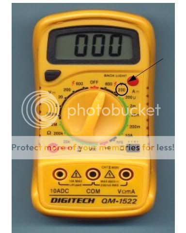
Put the black probe in the ground socket and the red probe in the smaller of the 2 vertical sockets. Readings should be between 118V to 123V. This is a good measure of how well the dock or marina is supplying power.
For checking 120VAC breakers on your panel, remove your panel and drop it down, revealing the backside of the breakers. Turn a breaker on, touch the black probe to the ground bus bar, and the red probe first to the input side of the breaker (to make sure the breaker is getting power), then to the output side. Both sides should read the same, approx. 120V.
Continuity- This feature is used to determine if there is a break in a wire, or basically an interruption in current flow. Set the dial on this setting, it looks like a little horn speaker. Most meters have an audible continuous beep when continuity is detected...
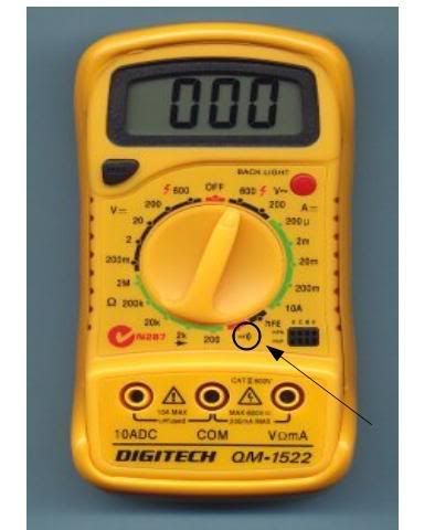
Touch either probe to one end of the wire, and the other to where you wish to check to see if it is continuous. When you have a good continuous wire, the digital readout should show 000-001. If it shows a reading of 020, chances are the wire is either loose at one end or the other, or there is heavy corrosion in the wire.
Probe Positions- These are the 2 sockets you plug the probes into...
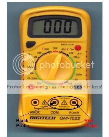
I also carry an extra black lead with an alligator clip on the end so I can clip it to a ground bus or battery terminal and not have to hold it.
Hope this gives you a little better understanding of how to use a multimeter, and how to further your troubleshooting skills...
I've been wiring boats at the OEM level for 16 years, as well as all the rewires, installs, and repairs in my side business. I have found the multimeter to be the tool I use the most, especially when it comes to troubleshooting.
Multimeter Basics
The Multimeter is probably the most important tool in your toolbox when you own an older boat. Over time, so much crap goes wrong electrically with your boat, it is almost impossible to troubleshoot and track down the causes of failures without one.
Now to some who have limited electrical experience, a multimeter may look daunting, when in reality, there are basically 3 functions used on the whole damn dial. DC Voltage, AC Voltage (for those that have shorepower or a generator), and Continuity.
12VDC- Obviously, this setting is used to measure the voltage present in a live circuit, as well as to determine the voltage level of a battery. Very straightforward, simply set the dial to this position...
Touch the black probe to a good ground and the red probe to the wire/terminal you wish to check for voltage.
If you have a 24V system (like a 24V trolling motor), you'll need to set the dial on 200.
120VAC- For those with shorepower, this is the setting used to check both your outlets and your breakers...
Put the black probe in the ground socket and the red probe in the smaller of the 2 vertical sockets. Readings should be between 118V to 123V. This is a good measure of how well the dock or marina is supplying power.
For checking 120VAC breakers on your panel, remove your panel and drop it down, revealing the backside of the breakers. Turn a breaker on, touch the black probe to the ground bus bar, and the red probe first to the input side of the breaker (to make sure the breaker is getting power), then to the output side. Both sides should read the same, approx. 120V.
Continuity- This feature is used to determine if there is a break in a wire, or basically an interruption in current flow. Set the dial on this setting, it looks like a little horn speaker. Most meters have an audible continuous beep when continuity is detected...
Touch either probe to one end of the wire, and the other to where you wish to check to see if it is continuous. When you have a good continuous wire, the digital readout should show 000-001. If it shows a reading of 020, chances are the wire is either loose at one end or the other, or there is heavy corrosion in the wire.
Probe Positions- These are the 2 sockets you plug the probes into...
I also carry an extra black lead with an alligator clip on the end so I can clip it to a ground bus or battery terminal and not have to hold it.
Hope this gives you a little better understanding of how to use a multimeter, and how to further your troubleshooting skills...
