kalm-c
Active member
Hey All....
Had the boat at the house for a bit today and what do ya know? I actually thought to take a couple of pics for you.....yes you!
So here ya go;
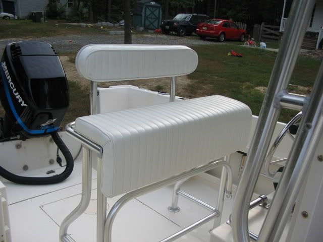
I got the leaning post/launcher built by Birdsall Marine who is local to me....they did a very nice job and I am glad I didn't live too long with out it as it has made fishing and hanging on the boat much more enjoyable.....it does kill some space, but as I read somewhere...perhaps here...."I have never seen someone fish from the center of the cockpit"
There is still good room for multiple anglers....it provides much needed storage as it flips open, I can lean against it while operating the second helm station, and I can stand on it for checking the trolling spread and seeking weed lines.
Also check out the boat name UnHooked as designed by our very own TomS!
And, while not a feature of this particular post, those of you who I know scrutinize the boatporn will ofcourse notice the wishbone outrigger holders from Lee's....they kick butt and make the old taco's I started with seem like childrens toys...nuff said.
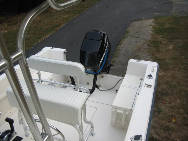
Install for the live well and leaning post started out with the live well in my shop. I carefully positioned the leaning post on top of the live well to be centered side to side and as far forward as possible to allow adequate access to the live well opening. Once set, holes were marked. Leaning post was removed, and the holes drilled. I applied some 5200 to the feet of the leaning post and with the aid of two other sets of hands carefully guided the post into place over the holes, using 1 screw in each foot to help align it as it came down.
Then each corner of the live well was slid off the work bench to allow me to put washers and nuts on the thru-bolts. Bada Bing.
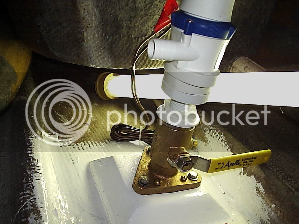
I forgot to mention that prior to all that I laid out with masking tape and pencil marks where the live well would live in the cockpit, and drilled holes in the deck for mounting, so that was already to go. I also figured out where the BIG holes in the deck would go for the water feed and light wires, as well as the drain elbow and tube, and after much measuring and thinking and smoking a couple of cigarettes and measuring a few more times while peering through the bilge, I busted out my trusty hole saw kit. The feed line and wires are run through a 1.5" hole cut with a hole saw, and the drain hole is a 5"hole also cut with a hole saw.
With the aid of a forklift and a couple of my guys, the whole sheebang was positioned over it's final resting place on saw horses while the plumbing connections were made. The wires and hoses were fished through the bilge, ontop of the fuel tank back the battery/bilge hatch.
So now I was ready to lower it into place, or so I thought....
I carefully applied 5200 to the underside of the livewell base perimeter, leaving small gaps in coverage around three screw holes so that I might locate it correctly, over the predrilled holes.
So here we go...my helpers lift the whole unit up and I remove the horses and they begin to slowly lower the unit as I pull excess hose and tubing and wiring through the bilge so that it doesn't get all kinked up under the well.....anyway.....we're just about there when it becomes apparent that with the hose connected to the drain elbow, there is just no way it can be lowered straight down to where it needs to go. AAARRRRGGGGG!
UP!UP!UP!
ok guys just hold her there for a minute.....
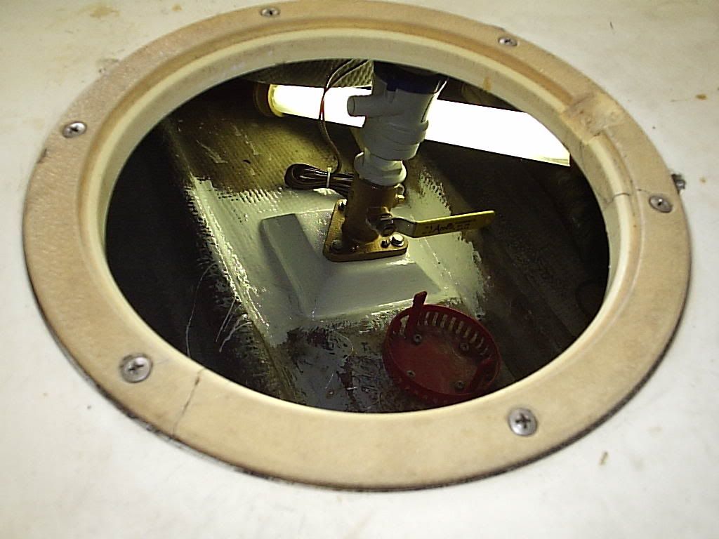
I grab a jig saw and cut an ugly u-shaped appendage on the aft side of my nice perfect 5"hole, while my guys are starting to sweat and groan holding this thing above my head...which now has a liberal spread of 5200 in various locations.....
ok bring her down slowly slowly.....perfect.
I secured it in place with four screws and filled the gaps in 5200 coverage by squeezing a good amount of it through the holes that were left blank for visibility, and then fastened off the rest of them....
At this point, all the hoses and wires are just coiled up in the bilge waiting for time,(hopefully this week), to drill and install the thru-hull water pick up and make the needed connections with the pump and all....while I am at it I will add a raw water wash down....just need to decide where that will live.
I apologize for the lack of install pictures, but when I get going, I get going and fall into the singleminded tunnelvision zone where cameras simply don't exist, and are therefore not even thought of...
BTW, for those of you who don't yet know, 5200 stays in the hair for a little over a week with daily washing and subconcious picking while at the computer.
Enjoy the rest of the summer!!!!
Had the boat at the house for a bit today and what do ya know? I actually thought to take a couple of pics for you.....yes you!
So here ya go;
I got the leaning post/launcher built by Birdsall Marine who is local to me....they did a very nice job and I am glad I didn't live too long with out it as it has made fishing and hanging on the boat much more enjoyable.....it does kill some space, but as I read somewhere...perhaps here...."I have never seen someone fish from the center of the cockpit"
There is still good room for multiple anglers....it provides much needed storage as it flips open, I can lean against it while operating the second helm station, and I can stand on it for checking the trolling spread and seeking weed lines.
Also check out the boat name UnHooked as designed by our very own TomS!
And, while not a feature of this particular post, those of you who I know scrutinize the boatporn will ofcourse notice the wishbone outrigger holders from Lee's....they kick butt and make the old taco's I started with seem like childrens toys...nuff said.
Install for the live well and leaning post started out with the live well in my shop. I carefully positioned the leaning post on top of the live well to be centered side to side and as far forward as possible to allow adequate access to the live well opening. Once set, holes were marked. Leaning post was removed, and the holes drilled. I applied some 5200 to the feet of the leaning post and with the aid of two other sets of hands carefully guided the post into place over the holes, using 1 screw in each foot to help align it as it came down.
Then each corner of the live well was slid off the work bench to allow me to put washers and nuts on the thru-bolts. Bada Bing.
I forgot to mention that prior to all that I laid out with masking tape and pencil marks where the live well would live in the cockpit, and drilled holes in the deck for mounting, so that was already to go. I also figured out where the BIG holes in the deck would go for the water feed and light wires, as well as the drain elbow and tube, and after much measuring and thinking and smoking a couple of cigarettes and measuring a few more times while peering through the bilge, I busted out my trusty hole saw kit. The feed line and wires are run through a 1.5" hole cut with a hole saw, and the drain hole is a 5"hole also cut with a hole saw.
With the aid of a forklift and a couple of my guys, the whole sheebang was positioned over it's final resting place on saw horses while the plumbing connections were made. The wires and hoses were fished through the bilge, ontop of the fuel tank back the battery/bilge hatch.
So now I was ready to lower it into place, or so I thought....
I carefully applied 5200 to the underside of the livewell base perimeter, leaving small gaps in coverage around three screw holes so that I might locate it correctly, over the predrilled holes.
So here we go...my helpers lift the whole unit up and I remove the horses and they begin to slowly lower the unit as I pull excess hose and tubing and wiring through the bilge so that it doesn't get all kinked up under the well.....anyway.....we're just about there when it becomes apparent that with the hose connected to the drain elbow, there is just no way it can be lowered straight down to where it needs to go. AAARRRRGGGGG!
UP!UP!UP!
ok guys just hold her there for a minute.....
I grab a jig saw and cut an ugly u-shaped appendage on the aft side of my nice perfect 5"hole, while my guys are starting to sweat and groan holding this thing above my head...which now has a liberal spread of 5200 in various locations.....
ok bring her down slowly slowly.....perfect.
I secured it in place with four screws and filled the gaps in 5200 coverage by squeezing a good amount of it through the holes that were left blank for visibility, and then fastened off the rest of them....
At this point, all the hoses and wires are just coiled up in the bilge waiting for time,(hopefully this week), to drill and install the thru-hull water pick up and make the needed connections with the pump and all....while I am at it I will add a raw water wash down....just need to decide where that will live.
I apologize for the lack of install pictures, but when I get going, I get going and fall into the singleminded tunnelvision zone where cameras simply don't exist, and are therefore not even thought of...
BTW, for those of you who don't yet know, 5200 stays in the hair for a little over a week with daily washing and subconcious picking while at the computer.
Enjoy the rest of the summer!!!!
Attachments
-
![3b8277bd-82a8-4622-ab23-3ee1218c806a[1].jpg](https://cdn.imagearchive.com/classicparker/data/attachments/2/2467-2c1ea9946e300218e29e849e91e936a3.jpg) 3b8277bd-82a8-4622-ab23-3ee1218c806a[1].jpg39.5 KB · Views: 3,452
3b8277bd-82a8-4622-ab23-3ee1218c806a[1].jpg39.5 KB · Views: 3,452 -
![9fbe276e-6407-4b66-807f-d2c499b8fc4a[1].jpg](https://cdn.imagearchive.com/classicparker/data/attachments/2/2466-d4b6370f297196eb7bbae8226cccd60a.jpg) 9fbe276e-6407-4b66-807f-d2c499b8fc4a[1].jpg47.4 KB · Views: 3,451
9fbe276e-6407-4b66-807f-d2c499b8fc4a[1].jpg47.4 KB · Views: 3,451 -
![68b17b31-5c3b-4fe1-b9fb-4036331907fa[1].jpg](https://cdn.imagearchive.com/classicparker/data/attachments/2/2465-d3ea7fa800d4ba2a33dafc12248dc17d.jpg) 68b17b31-5c3b-4fe1-b9fb-4036331907fa[1].jpg40.1 KB · Views: 3,451
68b17b31-5c3b-4fe1-b9fb-4036331907fa[1].jpg40.1 KB · Views: 3,451 -
![73e736ab-e052-4a01-ab29-46ed22d02c39[1].jpg](https://cdn.imagearchive.com/classicparker/data/attachments/2/2464-59acab0b5e0d88136025454ab1600053.jpg) 73e736ab-e052-4a01-ab29-46ed22d02c39[1].jpg50.5 KB · Views: 3,448
73e736ab-e052-4a01-ab29-46ed22d02c39[1].jpg50.5 KB · Views: 3,448 -
![ac515f88-8d13-405f-ad6a-13eb74f4d716[1].jpg](https://cdn.imagearchive.com/classicparker/data/attachments/2/2463-baef53552323a631f92e7b1b972f9654.jpg) ac515f88-8d13-405f-ad6a-13eb74f4d716[1].jpg54.2 KB · Views: 3,448
ac515f88-8d13-405f-ad6a-13eb74f4d716[1].jpg54.2 KB · Views: 3,448 -
![e896ef08-2ec5-4e04-a907-6d0845948d9e[1].jpg](https://cdn.imagearchive.com/classicparker/data/attachments/2/2462-b97fa07b63b7be42c8f46eba6e1bdb35.jpg) e896ef08-2ec5-4e04-a907-6d0845948d9e[1].jpg85 KB · Views: 3,449
e896ef08-2ec5-4e04-a907-6d0845948d9e[1].jpg85 KB · Views: 3,449