Mark, couple of thoughts. First, I understand wanting to move all possible weight forward and agree with that. Based on your diagram I’m not sure where the ARC switch is located but I’m assuming in the stern as the engine harness kinda dictates that and changing them to a large gauge wire for longer runs would be required and might not be doable? Second, make sure you check the spec on the negative bus in the bilge if you are reusing one. You are going to be running main grounds through it and then up to the battery’s, it may be handling more AMPS than just grounds for pumps etc...? Just make sure you gauge all of those battery cables large enough with those long runs from the Net bus/pos bus/ARC in the stern(depending on how you are doing it?). 12V is sensitive to voltage drops and you also don’t want melting wires, lol. As for venting battery’s in the cabin? That’s a tough one as you also have a burning heating system in the cabin. Safety first on a boat? You will have to make that call? I’m sure I’ve told you stuff you already know but thought I’d give you my 2 cents as they say.

You are using an out of date browser. It may not display this or other websites correctly.
You should upgrade or use an alternative browser.
You should upgrade or use an alternative browser.
1994 Parker 2320 extended cabin open back project
- Thread starter mheltunen
- Start date


Help Support Classic Parker Boat Forum:
This site may earn a commission from merchant affiliate
links, including eBay, Amazon, and others.
shawnee83":3zlhxlwv said:Mark, couple of thoughts. First, I understand wanting to move all possible weight forward and agree with that. Based on your diagram I’m not sure where the ARC switch is located but I’m assuming in the stern as the engine harness kinda dictates that and changing them to a large gauge wire for longer runs would be required and might not be doable? Second, make sure you check the spec on the negative bus in the bilge if you are reusing one. You are going to be running main grounds through it and then up to the battery’s, it may be handling more AMPS than just grounds for pumps etc...? Just make sure you gauge all of those battery cables large enough with those long runs from the Net bus/pos bus/ARC in the stern(depending on how you are doing it?). 12V is sensitive to voltage drops and you also don’t want melting wires, lol. As for venting battery’s in the cabin? That’s a tough one as you also have a burning heating system in the cabin. Safety first on a boat? You will have to make that call? I’m sure I’ve told you stuff you already know but thought I’d give you my 2 cents as they say.
Some very good points to consider and I appreciate the feedback. The ACR and battery switch will all be moved into the compartment under the captains seat. Regarding my negative buss, my vessel did not come with one so I installed a 245 amp blue seas buss last year (the largest they make). The cabling to the back I intend to use 1AWG which Greg’s marine wire rates at 245 Amp so that should be sufficient. For the house wiring and cabling for the batteries i plan on using 2 AWG. I do not like electrical issues and want to do it correctly. Regarding the venting I’m still working that out. I’m adding some vents to the compartments that will vent out to the rear deck. From my research the only time the hydrogen from off gassing becomes dangerous is when it collects in a confined (small area) space and has a source of ignition (spark). Obviously then it is an explosion risk. Due to hydrogens nature it is very light and given any source to go out it will. The health dangers from battery off gassing are (from my understanding and research) very low. So I intend to create a path for the gas to evacuate. The negligible amount that indeed vents into the pilot house area should vent out thru my canvas. Again this is the information I’ve collected thru my research. I want this install to be as safe a possible for both me and my passengers. If I’m indeed incorrect on my assumptions please let me know.
Sent from my iPhone using Tapatalk
That all sounds good. It sounds like you used the same Blue Seas bus that I installed when I did mine. So I guess you are going to install another bus for the positive from the engine harness and then run the heavy guage from there up to the ARC switch under the seat? That will work IMO. You sure are getting a lot done on your boat since you got it. Good luck with this project.
Attachments


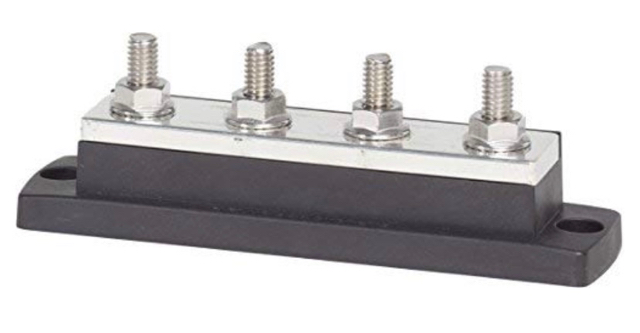
Thank you and yes, it’s been a long but enjoyable process. To be honest I probably enjoy working on the boat as much as using it. Regarding my positive wire from the outboards, that’s precisely my plan. A heavy buss in the stern for the positive connection point for the outboards.Here are the buss bars I used in the stern, both are 250 amp rating with 3/8” studs:

And here is what I’m going to use as my coupling point for the outboard(s) power:
Sent from my iPhone using Tapatalk
And here is what I’m going to use as my coupling point for the outboard(s) power:
Sent from my iPhone using Tapatalk
- Joined
- Mar 19, 2008
- Messages
- 6,066
- Reaction score
- 166
On edit
I do not think batteries let off much gas during normal use and charging. It is during over charging when batteries become hot and produce a lot of gas. . During non use time, open the hatch.
Sent from my iPad using Tapatalk
I do not think batteries let off much gas during normal use and charging. It is during over charging when batteries become hot and produce a lot of gas. . During non use time, open the hatch.
Sent from my iPad using Tapatalk
- Joined
- Mar 19, 2008
- Messages
- 6,066
- Reaction score
- 166
Stupid questions What is the white round object on top and round metal object on bottom left?
Sent from my iPad using Tapatalk
Sent from my iPad using Tapatalk
Brent":3555cdb0 said:I think batteries let off much gas during normal use and charging. It is during over charging when batteries become hot and produce a lot of gas. . During non use time, open the hatch.
Sent from my iPad using Tapatalk
I have an onboard charger installed on the vessel now and when it’s plugged in I always open the hatch doors so they can ventilate. I totally agree
Sent from my iPhone using Tapatalk
Yes Mark, same base as your bus and 250A, but I needed the smaller ring terminal points also for various other grounds like fuel tank, bilge pump etc...that we’re back there. Green one is the case ground for my battery charger. Good plan and moving the weight forward is also good, especially with the kicker. Good offset with the battery’s. Keep the pics coming on the project.
shawnee83":2xldzz0d said:Yes Mark, same base as your bus and 250A, but I needed the smaller ring terminal points also for various other grounds like fuel tank, bilge pump etc...that we’re back there. Green one is the case ground for my battery charger. Good plan and moving the weight forward is also good, especially with the kicker. Good offset with the battery’s. Keep the pics coming on the project.
I will keep updating as I go. I appreciate everyone’s feedback. Thanks
Sent from my iPhone using Tapatalk
- Joined
- Mar 19, 2008
- Messages
- 6,066
- Reaction score
- 166
You need a bigger boat and 2 footitis. A 2520
Sent from my iPad using Tapatalk
Sent from my iPad using Tapatalk
Brent":z1rhbuko said:You need a bigger boat and 2 footitis. A 2520
Sent from my iPad using Tapatalk
Perhaps some day. I would like twin outboards but 4 kids puts a crimp on the budget.
Sent from my iPhone using Tapatalk
- Joined
- Mar 19, 2008
- Messages
- 6,066
- Reaction score
- 166
Yep that certainly will. I can’t imagine you selling it
Sent from my iPad using Tapatalk
Sent from my iPad using Tapatalk
Brent":3d9wwrj4 said:Yep that certainly will. I can’t imagine you selling it
Sent from my iPad using Tapatalk
Agreed. I intend to hold on to her for a long time and I’m setting it up accordingly.
Sent from my iPhone using Tapatalk
Billman
Member
I've been following along, waiting for updates. I would much rather have the open back configuration. Well done Sir!
Billman":3r7i9337 said:I've been following along, waiting for updates. I would much rather have the open back configuration. Well done Sir!
Thank you very much. It’s been a fun project.
Sent from my iPhone using Tapatalk
Second vhf (second hand) installed, please excuse the mess:

Intake vents installed for heater:

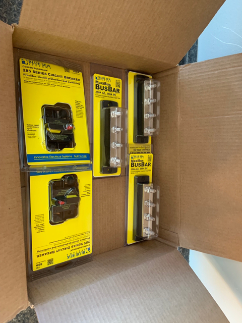
Parts for the battery relocation starting to come in, wire ordered as well (ouch):
Sent from my iPhone using Tapatalk
Intake vents installed for heater:
Parts for the battery relocation starting to come in, wire ordered as well (ouch):
Sent from my iPhone using Tapatalk
Exhaust extension was delivered today. I mocked it up to make sure the length will work. It looks like the length is sufficient . Next I need some high temp exhaust caulk, followed by exhaust wrap. Somehow I need to come up with some type of bracket to support the exhaust pipe. I’ll have to think about that some more .

Sent from my iPhone using Tapatalk
Sent from my iPhone using Tapatalk
I had some time today and started setting up my battery (relocated) panel. The three breakers feed the house fuse panel, the house switch panel and the third one feeds the stern. All the battery wiring is 2AWG except 1/0 for the engine start circuit.

Sent from my iPhone using Tapatalk
Sent from my iPhone using Tapatalk
Nice clean instal Mark. Looks great.
albiejunkie
Well-known member
Agreed. Very nice layoutshawnee83":3w0pme1l said:Nice clean instal Mark. Looks great.
Sent from my SM-G930V using Tapatalk